Tuesday, 15 November 2022

Felezjoo Detector with no counter

 This is my new compact Felezjoo detector with 3.7Vdc battery backup charging from any mobile phone charger  including  C-Type. 

Some changes like i used 2N7000 instead FET BS170  and instead of BC337 i used 2N3904

Voltage buckup module used to stepup the voltages to 18Vdc, 1x1 coil used  


Tuesday, 10 May 2022

Arduino SIM800L IMEI CHANGER

📡 Arduino SIM800L IMEI Configuration & Setup Guide

📌 Overview

This guide covers querying and updating the IMEI parameter on SIM800L GSM modules using standard AT commands, along with recommended power supply references.

Note: Modifying or cloning IMEI numbers may be restricted or illegal in certain jurisdictions depending on local telecommunication regulations and device registration frameworks (e.g., PTA / DIRBS). Ensure compliance with local laws before modifying GSM device identifiers.

1. 🔍 How to Read/Find Current IMEI

To retrieve the current IMEI string from a SIM800L module over AT commands:

C++
delay(4000);
SIM800L.println("AT+GSN"); // Queries the IMEI number
delay(1000);

2. ⚙️ AT Command Code Example

Below is a simple Arduino sketch demonstrating sending the AT+SIMEI command to set a target IMEI string:

C++
#include <SoftwareSerial.h>

// Define SoftwareSerial pins (Rx, Tx)
SoftwareSerial SIM800L(10, 11); 

void setup() {
  Serial.begin(9600);   // Hardware Serial for Debugging
  SIM800L.begin(9600);  // Software Serial for SIM800L
  
  delay(2000);

  // Send command to set desired 15-digit IMEI
  SIM800L.println("AT+SIMEI=863789000008218"); 
}

void loop() {
  // Read responses from SIM800L and print to Serial Monitor
  if (SIM800L.available()) {
    Serial.write(SIM800L.read());
  }
}

🎥 Reference Videos

⚡ Power Supply Reference


Sunday, 5 September 2021

Arduino Car Alternator to Brushless Motor conversion

 Arduino Car Alternator to Brushless Motor conversion 

Below is the simple Arduino control car alternator working as a powrfull motor 
Here simple ESC 30 Amps were used 
1). Need 12VDC connected to the internal coil of alternator first

2). 12VDC also need to be  connected to ESC 

3). Arduino will get 5V from the ESC buit-in 5VDC output

4). ESC connected to arduino  pin # 8

5). 10 K resistor connected to  arduino A0

https://web.facebook.com/ksfelectronics

servo esc;    

void setup()

{

esc.attach(8); 

esc.writeMicroseconds(1000); 

}

void loop(){

int val;                           

val= analogRead(A0);   

val= map(val, 0, 1023,1000,2000);                                                          

esc.writeMicroseconds(val);      

}

Check the video:

https://www.youtube.com/watch?v=LzQ_vyZUGTU


Friday, 13 November 2020

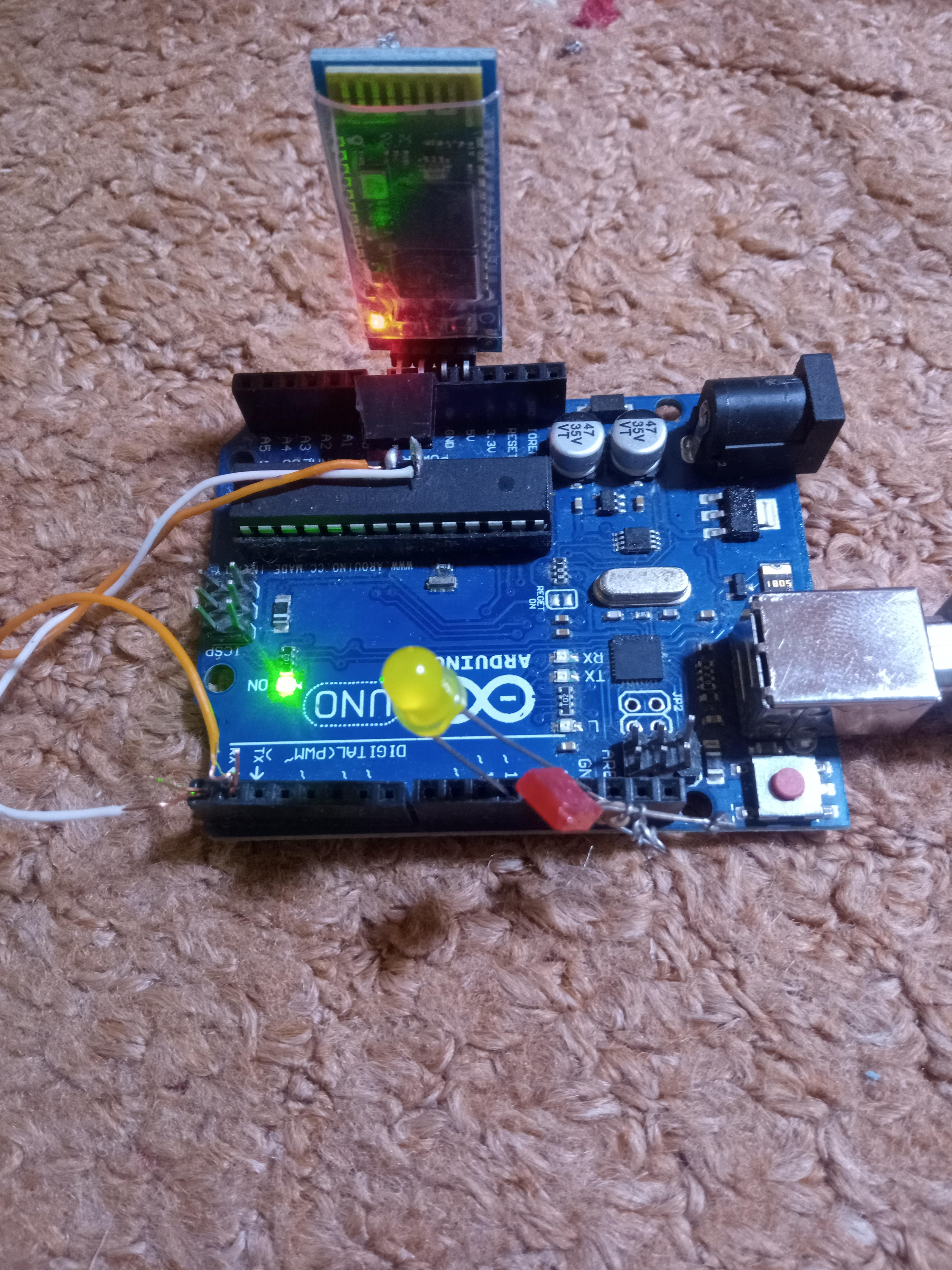
Arduino Bluetooth Remote control


Complete Arduino Bluetooth Remote Control Home Automation Project (with Custom APK)

This project provides a complete, easy-to-build wireless home automation system controlled via Bluetooth using a custom Android application.

📺 Project Demonstration Video

📦 Required Components & Hardware

  1. Arduino Nano microcontroller

  2. Bluetooth Module (such as HC-05 or HC-06)

  3. 5V Relay Module (4-channel configuration)

  4. NPN Transistor (e.g., BC547 or 2N2222 for relay driving)

  5. 1k Resistor (for transistor base current limiting)

  6. 5V DC Power Supply

🔌 Wiring & Pin Connections

  • Bluetooth Module: Connected to Pins 2 and 3 of the Arduino Nano (using SoftwareSerial).

  • Relay Control Pins: Connected to Arduino Analog Pins configured as digital outputs:

    • Relay 1: Pin A1

    • Relay 2: Pin A2

    • Relay 3: Pin A3

    • Relay 4: Pin A4

💻 Arduino Source Code

Copy and upload the following sketch to your Arduino Nano:

C++
#include <SoftwareSerial.h>

// Bluetooth module connected to pins 2 (RX) and 3 (TX) of Arduino
SoftwareSerial mySerial(2, 3); 

#define relay1 A1
#define relay2 A2
#define relay3 A3
#define relay4 A4

char val;

void setup() {
  pinMode(relay1, OUTPUT);
  pinMode(relay2, OUTPUT);
  pinMode(relay3, OUTPUT);
  pinMode(relay4, OUTPUT);
  
  digitalWrite(relay1, LOW);
  digitalWrite(relay2, LOW);
  digitalWrite(relay3, LOW);
  digitalWrite(relay4, LOW);
  
  mySerial.begin(9600);
  Serial.begin(9600);
}

void loop() {
  // Check incoming serial data from Bluetooth Android App
  while (mySerial.available() > 0) {
    val = mySerial.read();
    Serial.println(val);
  }

  // Relay Turn ON Commands
  if (val == '1') {
    digitalWrite(relay1, HIGH);
  } 
  else if (val == '2') {
    digitalWrite(relay2, HIGH);
  } 
  else if (val == '3') {
    digitalWrite(relay3, HIGH);
  } 
  else if (val == '4') {
    digitalWrite(relay4, HIGH);
  }

  // Relay Turn OFF Commands
  else if (val == 'A') {
    digitalWrite(relay1, LOW);
  } 
  else if (val == 'B') {
    digitalWrite(relay2, LOW);
  } 
  else if (val == 'C') {
    digitalWrite(relay3, LOW);
  } 
  else if (val == 'D') {
    digitalWrite(relay4, LOW);
  } 

}                                                                                                                                                 


MIT Codes


Saturday, 4 April 2020

GPS Car Tracker

GPS Car Tracker 


Price: 20,000 PKR

No Annual charges with android App

Specifications.

 1). Track your car through GPS coordinates.
 2). Car door open alert.
 3). Car Bonnet open alert.
 4). Car Battery terminal open alert.
 5). Car engine On/Off.
 6). Car engine Start/Stop.
 7). Car Door lock Open/Close.
 8). Car Horn On/Off.
 9). Car Lights On/Off.
10). Built-in MIC.
11). Geofence
---------------------------------------------------------------------------------

Contact me at:


Whatsapp:  +923127800081

-------------------------------------------------------------------------------

PIM 2 Metal Detector:


---------------------------------


Check video:


https://www.youtube.com/watch?v=2HWzavLhwaA&t=54s


                                      Easy Andriod simple app 


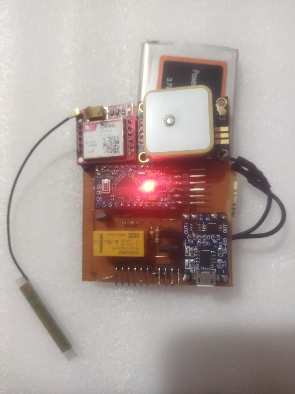
In this project following parts were used1). micro controller Atmega328
2). Sim900A.
3). Neo GPS module
4). DC to DC boost power supply.
5). 12vdc to 5vdc converter (car charger).
6). 3.7V, 1800 mAh , (mobile battery).
7). 5V relays


Monday, 21 October 2019

FM Transmitter 25 Watts ( 88 - 108 MHz)

This Transmitter is made from the MP3 modulator with having 5 stages

with a maximum 25 Watts RF power


Driver circuit between modulator & RF section below 

coil will be  0.1 mH