Tuesday 11 June 2013

ON/OFF Switch using DPDT relay (220V) & PC mouse

In this circuit one relay & PC mouse were used, no such a electronic circuit were used  , here 2 micro switch 
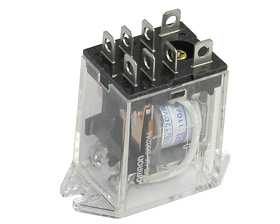
& 8 pin DPDT relay 220 v used, if you see the connections of the relay you will see that main AC 220 were connected to points 7 & 8, another wire taken from pin 6 to pin 2 through micro switch (OFF), 2 wires were taken from pins 8 & 2 to the micro switch (ON), Device to be controlled wires are taken from pins 3 & 1.In the presence of 220 AC  if we press ON switch relay will energize while current flow through pin 7 & 2, where current will flow through switch from pin 8 to pin 2  , both 7 & 2 pins are the rely energizing points ,when relay energized it will remain energize due to pin 8 & 6 to pin 2 through micro switch ( OFF ) , because current will flow from pin 8 to pin 6 ( now connected due to relay energized ) .By pressing switch OFF supply will be disconnected between pin 6 & 2, relay will become in normal condition


Tuesday 4 June 2013

Auto Changeover from Inverter / Generator to Mains Supply

Below is the Inverter & mains change over circuit, in this circuit  both Inverter supply & mains supply combined which is called UPS , for this purpose  8 pin DPDT relay (220 V ) were used as explain in the diagram ,
Blue wires are for Inverter ON & OFF switch, in absence of MAINS supply Inverter will be in ON condition (pin 1 connected to 4), as can be see in diagram, 
One of the wire from mains, Inverter & output are kept common,
Pin # 8 is common for 5 & 6 pin, where main connected to pin 6 & Inverter to pin 5.
Green wires to pins 2 & 7 are relay energizing points, where both wires are connected to the mains,
In absence of mains Inverter will be in on condition due to pin 1 & 4 connected, supply from Inverter
Will be available due to pins 5 & 8 connected each other,
In the other hand if  mains supply came relay will be energize due to pins 2 & 7 , pins 6 will connect to 8,
Pin 1 will be disconnected from 4, Inverter will be off.
You use generator instead of Inverter but the Technic is same


Keep in mind that one wire from  mains supply , invertor & output must common 


http://obaidkakar.blogspot.com/2015/04/delta-pulse-2-metal-detector.html

http://obaidkakar.blogspot.com/2015/03/delay-off-timer-3vdc-to-5vdc.html


Monday 3 June 2013

Over voltage protection circuit (passive)

Below circuit is about over voltage protection related, here 2 relays (220 v) are used of 14 pins, pins # 13 & 14 of both relays are kept in series, and both 13 pin of 1st relay & 14 pin of 2nd relay connected direct to main AC, at the other end pins 9 to 12 of both relays connected to one of the main input, output taken from pins 1 to 4 , Normally all pins 9 to 12 of both relays connected to pins 1 to 4,It means that in normal condition relay will allow supply  to house , normal 220 V AC voltage is unable to energize both relay in series, but if any  over voltage (double phase ) observed at the input , both relay will be energized & supply will be disconnected .


Sunday 2 June 2013

GSM Remote Control


Today I am going to introduce a simple mobile phone remote control circuit which is so simple that everybody can easily assemble it, In this circuit following items which are easily available every where. here  Mobile phone set,  Relay (3V DC),  Capacitor 4700 uf, 25 v will required I think 3V DC relay is not difficult to find in the market. In this circuit 2 wires are taken from the mobile vibrator points, these points are +ve & -ve , Simply connect both +ve & -ve output to the relay points. There is enough voltage from the vibrator point to operate the relay. Once you call the said mobile you will observe the relay will not continuously ON & OFF due to signal from the vibrator output , here we need continuous relay energization while calling mobile, for this we have to add a capacitor in the circuit parallel to the relay points, but should care about the polarity of capacitor, Capacitor +ve shout be connected to +ve point of vibrator, this circuit can be used for door open, car safety,