Complete Bluetooth Remote control Project
Arduino Bluetooth Remote control with APK
A great Bluetooth Remote control for your home automation ,
...............................................................................................
Check Video:
https://m.youtube.com/watch?v=j2HYM4YbRK0
1). 1k Resister
2). Any NPN transister
3). 5 Volt Relay
4). Arduino nano
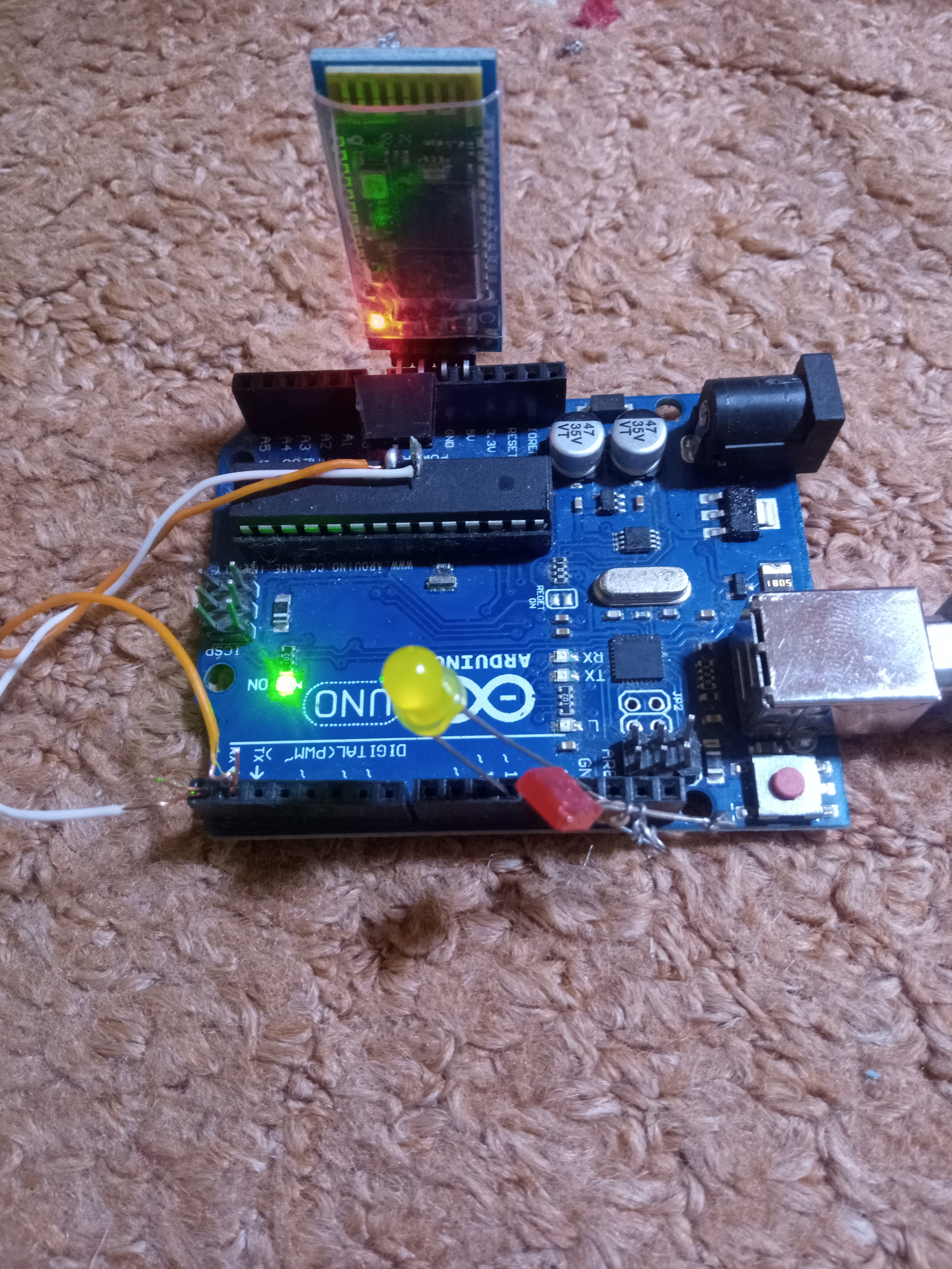
5). Bluetooth module
6). 5 volt power supply
7). Arduino 6 & 7 pin used with bluetooth


MIT Codes

Below are the Arduino codes
#include <SoftwareSerial.h>
SoftwareSerial mySerial(2, 3); Bluetooth module connected to 2,3 pins of ardiuno
#define relay1 A1
#define relay2 A2
#define relay3 A3
#define relay4 A4
char val;
void setup() {
pinMode(relay1,OUTPUT);
pinMode(relay2,OUTPUT);
pinMode(relay3,OUTPUT);
pinMode(relay4,OUTPUT);
digitalWrite(relay1,LOW);
digitalWrite(relay2,LOW);
digitalWrite(relay3,LOW);
digitalWrite(relay4,LOW);
mySerial.begin(9600);
Serial.begin(9600);
}
void loop() {
//cek data serial from bluetooth android App
while ( mySerial.available() >0 ) {
val = mySerial.read();
Serial.println(val);
}
//Relay is on
if( val == '1' ) {
digitalWrite(relay1,HIGH); }
else if( val == '2' ) {
digitalWrite(relay2,HIGH); }
else if( val == '3' ) {
digitalWrite(relay3,HIGH); }
else if( val == '4' ) {
digitalWrite(relay4,HIGH); }
//relay all on
//relay is off
else if( val == 'A' ) {
digitalWrite(relay1,LOW); }
else if( val == 'B' ) {
digitalWrite(relay2,LOW); }
else if( val == 'C' ) {
digitalWrite(relay3,LOW); }
else if( val == 'D' ) {
digitalWrite(relay4,LOW); }
//relay all off
}