Sunday, 19 August 2018

ARDUINO FM RADIO

Here is a simple FM radio with Ardiuno  board ,
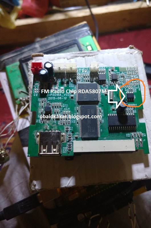
Which required popular Radio module called  RDA5807M.

The RDA5807M series support frequency range is from 50MHz to 115MHz.

Easily available in the market

i simply find this module in MP3 players available in the market ,

this modules is without 32khz crystal, you need to placed this crystal on the IC 6 pin & to the ground

You must have Libraries like -------Wire.h ----    TEA5767Radio.h   -------    LiquidCrystal.h   

Here in Code TEA5767Radio were used , it will support RDA5807M Chip.

Also remember these two pins must be proper

  * Arduino Pin A5  =  Radio Chip Pin SDA  
 * Arduino Pin A4   =  Radio Chip Pin SCL   

1 ----> Arduino SDA
2 ----> Arduino SCL
3 ----> GND
5 ----> +5V
6 ----> GND
7 ----> Audio out (right channel)
8 ----> Audio out (left channel)
10 ---> Antenna

 * LCD RS pin to digital pin 12
 * LCD Enable pin to digital pin 11
 * LCD D4 pin to digital pin 5
 * LCD D5 pin to digital pin 4
 * LCD D6 pin to digital pin 3
 * LCD D7 pin to digital pin 2
 * LCD R/W pin to ground
 * Arduino SDA PIN A5
 * Arduino SCL PIN A4
 * ends to +5V and ground
 * UP SEARCH (A0)
 * DOWN SEARCH (A1)
-----------------------------------------------------------------
#include <Wire.h>                             
#include <TEA5767Radio.h>                     
#include <LiquidCrystal.h>                   
                                             
                                             
TEA5767Radio radio = TEA5767Radio();         
LiquidCrystal lcd(12, 11, 5, 4, 3, 2);           
float frequency = 0;                         
int fUP = A0;                                 
int fDOWN = A1;                             
int count = 0;                                 


void setup()
{
  delay(1000);
  Wire.begin();
  frequency = 96.0;                       //starting frequency

  radio.setFrequency(frequency);
  lcd.begin(16,2);
  lcd.clear();
  lcd.setCursor(0,0);
  lcd.print("FM: ");
  lcd.setCursor(0, 1);
  lcd.print(frequency);

}

void loop()
{

  if(digitalRead(fUP))                   
  {
    count=0;
    while (digitalRead(fUP))
    {
      count++;
      if(count > 0 && count <= 6)       
      {
        frequency += 0.1;
        frequencyUpdate();
        delay(200);
      }
      else if (count > 6 && count <= 2) 
      {
        frequency += 0.1;
        frequencyUpdate();
        delay(80);
      }
      else                             
      {
        frequency += 0.1;
        frequencyUpdate();
        delay(5);
      }
    }

  }


   if(digitalRead(fDOWN))                 
   {
     count = 0;
    while (digitalRead(fDOWN))         
    {
      count--;
      if(count < 0 && count >= -6)
      {
        frequency -= 0.1;
        frequencyUpdate();
        delay(200);
      }
      else if (count < -6 && count >= -12)
      {
        frequency -= 0.1;
        frequencyUpdate();
        delay(80);
      }
      else                               
      {
        frequency -= 0.1;
        frequencyUpdate();
        delay(5);
      }
    }
   }

}


void frequencyUpdate()                    //this function changes the frequency of the station, is called by preset and frequency up/down conditions.
{
  frequency = constrain(frequency, 50.0, 115.0);     //50MHz to 115MHz.
  lcd.setCursor(0,0);
  lcd.print("KSF FM:");
  lcd.setCursor(0,1);
  lcd.print(frequency);
  radio.setFrequency(frequency);
}


Monday, 9 July 2018

2 PHASE AC STABILIZER ( ARDUINO BASED)

Below Mentioned circuit


#include <LiquidCrystal.h>

// number of analog samples to take per reading, per channel
#define NUM_SAMPLES 30
// voltage divider calibration values
#define DIV_1    58.13465
#define DIV_2    58.07185
#define DIV_3    58.07185
#define DIV_4    58.07185
// ADC reference voltage / calibration value
#define V_REF    4.991
LiquidCrystal lcd(12, 11, 5, 4, 3, 2);
int sum[4] = {0};                // sums of samples taken
unsigned char sample_count = 0;  // current sample number
float voltage[4] = {0.0};        // calculated voltages
char l_cnt = 0;                  // used in 'for' loops

int pinButton = 6; //the  button -- 12 PIN
int LED = 7; //the pin we connect the LED--13 PIN
int RELAY = 8; //the pin we connect the RELAY --14 PIN
int ON = 9; //the pin we connect the --15 PIN
int OFF = 10; //the pin we connect the --16 PIN
int phase1 = A0; //the pin we connect the -- 23 PIN
int phase2 = A1; //the pin we connect the -- 24 PIN
void setup()

{

    lcd.begin(16, 4);     // main lcd starting point
    lcd.setCursor(0,1);
    lcd.print("KSF ELECTRONICS");
    delay(1000);
    lcd.clear();
    lcd.setCursor(0,1);
    lcd.print(" obaidkakar.");
    lcd.setCursor(0,2);
    lcd.print(" blogspot.com");
    delay(1000);
    lcd.clear();
    lcd.setCursor(0,0);
    lcd.print("   WARNING   ");
    lcd.setCursor(0,1);
    lcd.print("After button on ");
    lcd.setCursor(0,2);
    lcd.print("Motor will start");
    lcd.setCursor(0,3);
    lcd.print("in 13 Seconds");
    delay(1000);
    lcd.clear();  // clear screen
    pinMode(pinButton, INPUT); //set the button pin as INPUT
    pinMode(LED, OUTPUT); //set the LED pin as OUTPUT
    pinMode(RELAY, OUTPUT); //set the LED pin as OUTPUT
    pinMode(ON, OUTPUT);
    pinMode(OFF, OUTPUT);
    pinMode(phase1, INPUT);
    pinMode(phase2, INPUT);
    Serial.begin(9600);
    }
    void loop()
    {
    // take a number of analog samples and add them up
    while (sample_count < NUM_SAMPLES) {
        // sample each channel A2 to A5
        for (l_cnt = 0; l_cnt < 4; l_cnt++) {
            sum[l_cnt] += analogRead(A2 + l_cnt); // input were given to lcd
        }
        sample_count++;
        delay(40);
    }
    // calculate the voltage for each channel
    for (l_cnt = 0; l_cnt < 4; l_cnt++) {
        voltage[l_cnt] = ((float)sum[l_cnt] / (float)NUM_SAMPLES * V_REF) / 1024.0;
    }
    // display voltages on LCD
    // each voltage is multiplied by the resistor network
    // division factor to calculate the actual voltage
    // voltage 1 - A (pin A2)
 
    lcd.setCursor(0, 0);
    lcd.print("SETTING ");
    lcd.print(voltage[2] * DIV_3, 1); // pin A4--Setting --27 PIN
    lcd.print(" AC ");
    lcd.setCursor(0, 1);
    lcd.print("PHASE1  ");
    lcd.print(voltage[0] * DIV_1, 1); // pin A2-- PHASE 1--25 PIN
    lcd.print(" AC ");
    lcd.setCursor(0, 2);
    lcd.print("PHASE2  ");
    lcd.print(voltage[1] * DIV_2, 1); // pin A3 --PHASE 2--26 PIN
    lcd.print(" AC ");
    lcd.setCursor(0, 3);
     lcd.print("OUTPUT  ");
    lcd.print(voltage[3] * DIV_4, 1); // pin A5--Output--28 PIN
    lcd.print(" AC ");
     if(voltage[1]== 0){
      lcd.clear();
    lcd.setCursor(0,1);
    lcd.print("PHASE2 MISSING  ");
 
     }
    if(voltage[0]== 0){
      lcd.clear();
    lcd.setCursor(0,2);
    lcd.print("PHASE1 MISSING  ");
 
    delay(10);
    }
 // voltage 4 - D (pin A5)
    // reset count and sums
    sample_count = 0;
    for (l_cnt = 0; l_cnt < 4; l_cnt++)
{
        sum[l_cnt] = 0;
    }
     int stateButton = digitalRead(pinButton); //read the state of the button
     int stateButton1 = digitalRead(voltage[0]); //read the state of the button
     int stateButton2 = digitalRead(phase2); //read the state of the button
     if(stateButton == 1 && stateButton1 ==1 &&  stateButton2 == 1 ) { //if is pressed+ all phases present then.
   
     digitalWrite(LED, HIGH); //write 1 or HIGH to led pin
     digitalWrite(ON, HIGH);
     digitalWrite(OFF, LOW);
     } else { //if not pressed
     digitalWrite(LED, LOW);  //write 0 or low to led pin
     digitalWrite(ON, LOW);
      digitalWrite(OFF, HIGH);
     delay(10000);
     } if(voltage[0] < voltage[2]) digitalWrite(RELAY, HIGH);
     else { digitalWrite(RELAY,LOW);
     delay(20);
   
     }
    }

Saturday, 3 March 2018

ARDUINO BASED UNINTERRUPTIBLE DC TO DC POWER SUPPLY

Microcontroller based DC to DC uninterruptible power supply below
Network of ICs 317 & 7805 limited high DC voltages 60 VDC  upto 5 VDC for the whole circuit working.
Here 16*4 LCD used , optocoupler 817 used to derive FET ,48 Vdc Relay used , 


Codes below

  // By Engineer Obaidullah Khan Kakar 28/2/2018
  #include <LiquidCrystal.h>
  #define NUM_SAMPLES 30
  #define DIV_1    58.13465
  #define DIV_2    58.07185
  #define DIV_3    58.0718
  #define DIV_4    58.07185
  #define V_REF    4.991
  LiquidCrystal lcd(12, 11, 5, 4, 3, 2);
  int sum[4] = {0};             
  unsigned char sample_count = 0;
  float voltage[4] = {0.0};     
  char l_cnt = 0;             
  #define led 8
  #define led 9
  #define led 10
  int sensorPin = A2;
  int sensorPin1 = A3;
  int sensorPin2 = A4;
  unsigned int sensorValue = 0;
  unsigned int sensorValue1 = 0;
  unsigned int sensorValue2 = 0;
  void setup(){
  lcd.begin(16, 4); 
  lcd.print("KSF ELECTRONICS");
  delay(700);
  lcd.clear();
  lcd.print("obaidkakar");
  lcd.setCursor(0,1);
  lcd.print(".blogspot.com");
  delay(800);
  lcd.clear();  // clear screen
 pinMode(8, OUTPUT);
  pinMode(9, OUTPUT);
  pinMode(10, OUTPUT);
  Serial.begin(9600);
}
void loop()
{
  while (sample_count < NUM_SAMPLES) {
   for (l_cnt = 0; l_cnt < 4; l_cnt++) {
   sum[l_cnt] += analogRead(A2 + l_cnt); // input were given to lcd
  }
    sample_count++;
    delay(40);
    }
    // calculate the voltage for each channel
    for (l_cnt = 0; l_cnt < 4; l_cnt++) {
        voltage[l_cnt] = ((float)sum[l_cnt] / (float)NUM_SAMPLES * V_REF) / 1024.0;
    }
     lcd.setCursor(0, 0);
    lcd.print("DC1    ");
    lcd.print(voltage[0] * DIV_1, 1); // pin A2
    lcd.print("VDC ");
    lcd.setCursor(0, 1);
    lcd.print("DC2   ");
    lcd.print(voltage[1] * DIV_2, 1); // pin A3
    lcd.print("VDC ");
    lcd.setCursor(0, 2);
    lcd.print("CUTOFF ");
    lcd.print(voltage[2] * DIV_3, 1); //pin A4
    lcd.print("VDC ");
   sample_count = 0;
    for (l_cnt = 0; l_cnt < 4; l_cnt++)
   {
     sum[l_cnt] = 0;
    }
   sensorValue = analogRead( sensorPin);
   sensorValue1 = analogRead( sensorPin1);
   sensorValue2 = analogRead( sensorPin2);
   delay(400);
   if(sensorValue>168) digitalWrite(8, LOW);
   delay(800);
   if(sensorValue>168) digitalWrite(9, HIGH);
   delay(800);
   if(sensorValue<164) digitalWrite(9, LOW);
   delay(800);
   if(sensorValue<164) digitalWrite(8, HIGH);
   delay(400);
   lcd.setCursor(0, 3);
   if(sensorValue>168) lcd.print("DC1 BATT CONECT  ");
   if(sensorValue<164) lcd.print("DC2 BATT CONECT ");
    }


Sunday, 28 January 2018

IRANIAN METAL DETECTOR - FelezJoo PI Metal Detector (FPI)


At first glance battery low alarm seen on the screen as if   12v given to detector for this  replace R19 value 22k to 18 k. 
But 18 Volts must be supplied to the detector for proper working. Also can work best on 24 VDC.

Delta Pulse 2 : https://obaidkakar.blogspot.com/2015/04/delta-pulse-2-metal-detector.html

My new  Title of the document Felezjoo detector  : 

https://obaidkakar.blogspot.com/2022/11/felezjoo-detector.html

WhatsApp : +923127800081

Video :  https://www.youtube.com/watch?v=RlMi2n-AguY


Price: 50,000 PKR


Check detector performance 
Click on below