Monday, 25 November 2013

Day Night Switch (Solid State)

Now a days LED lights are so common everywhere, you can direct connect it with battery no need any UPS / invertor, I decided to installed such power LED light at roof top along day night switch, so I design a simple switch circuit with minimum components, I found it very reliable & stable, a high power FET were used, you don’t worry about the FET you can use any powerful N-Channel FET available in the market which are mostly used in UPS. Heat sink insulation Recommended between FET & heat sink if not no issue . I used FET 47N60C3 ,  LDR,  Variable resistor 305 mega ohms,   Pressure 12 VSeparate heat sinks for both FET & LED are recommended.  


Monday, 23 September 2013

DELTA PULSE 3 METAL DETECTOR

Delta Pulse 3 metal detector (Pulse induction) is a versatile & professional detector, same like delta pulse 2,This detector have a LCD screen facility,  actually the every step like in the delta pulse 2 is done here by the micro controller , pulse for the Coil driven transistor FET , the delays like in delta pulse 2 by the 4538 also done by the micro controller, other IC used for the interface between the output result , battery power to the microcontroller , GLCD used in this project is used where you have facility to monitor every necessary data . only basic IC TL081 used for signal amplification,   


Tuesday, 3 September 2013

DTMF Remote Control GSM Based

It was a big experiment for testing this circuits, a very versatile remote control circuit which is consist of DTMF decoder IC 8870 & 4 bit BCD to decimal 4028 IC, Four binary outputs are connected to the inputs of BCD to decimal 4028 IC .You can control up to 9 appliances by this circuit, out puts will be in latched form.Mobile phone can be easily used with circuits, all the keypad button 1 to 9 will be used.i used this circuit for Car GPS remote control ,actually the output from the 4028 will be a latched on state due to the IC 8870 , this IC have latched output .any pin will remain active untile other code were not given the decoder by the any source like mobile or any other source.


Friday, 12 July 2013

PTCL EVO Wingle 9.1 Mb USB (Built-in Wi-Fi) powered by mobile battery (like a portable 3G EVO Nitro Cloud)

It was a time when there was no Battery Backup for any internet USB device , then i decided to design a trick to power the USB from the mobile battery , a USB female pin were for USB to be powered , dual color LED were use for indicating charging & on indication , a slide switch use to on/off the USB,a small pin female were used to charge the battery, a very simple project every guy can assembled it, plz care of USB & charger pin polarity, with high apms battery up to 5 to 8 hours backup can be expected , 


It can be easily charge by using common Nokia charger, don’t worry about over charging there is built in cutoff circuit in side every mobile battery,
One thing I missed that there should be USB pin charging facility and schematic of this project, no issue I will add it soon. 


Tuesday, 11 June 2013

ON/OFF Switch using DPDT relay (220V) & PC mouse

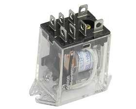
In this circuit one relay & PC mouse were used, no such a electronic circuit were used  , here 2 micro switch & 8 pin DPDT relay 220 v used, if you see the connections of the relay you will see that main AC 220 were connected to points 7 & 8, another wire taken from pin 6 to pin 2 through micro switch (OFF), 2 wires were taken from pins 8 & 2 to the micro switch (ON), Device to be controlled wires are taken from pins 3 & 1.In the presence of 220 AC  if we press ON switch relay will energize while current flow through pin 7 & 2, where current will flow through switch from pin 8 to pin 2  , both 7 & 2 pins are the rely energizing points ,when relay energized it will remain energize due to pin 8 & 6 to pin 2 through micro switch ( OFF ) , because current will flow from pin 8 to pin 6 ( now connected due to relay energized ) .By pressing switch OFF supply will be disconnected between pin 6 & 2, relay will become in normal condition


Tuesday, 4 June 2013

Auto Changeover from Inverter / Generator to Mains Supply

Below is the Inverter & mains change over circuit, in this circuit  both Inverter supply & mains supply combined which is called UPS , for this purpose  8 pin DPDT relay (220 V ) were used as explain in the diagram ,
Blue wires are for Inverter ON & OFF switch, in absence of MAINS supply Inverter will be in ON condition (pin 1 connected to 4), as can be see in diagram, 
One of the wire from mains, Inverter & output are kept common,
Pin # 8 is common for 5 & 6 pin, where main connected to pin 6 & Inverter to pin 5.
Green wires to pins 2 & 7 are relay energizing points, where both wires are connected to the mains,
In absence of mains Inverter will be in on condition due to pin 1 & 4 connected, supply from Inverter
Will be available due to pins 5 & 8 connected each other,
In the other hand if  mains supply came relay will be energize due to pins 2 & 7 , pins 6 will connect to 8,
Pin 1 will be disconnected from 4, Inverter will be off.
You use generator instead of Inverter but the Technic is same


Keep in mind that one wire from  mains supply , invertor & output must common 


http://obaidkakar.blogspot.com/2015/04/delta-pulse-2-metal-detector.html

http://obaidkakar.blogspot.com/2015/03/delay-off-timer-3vdc-to-5vdc.html