Friday, 30 December 2016

Arduino UNO simple experiments


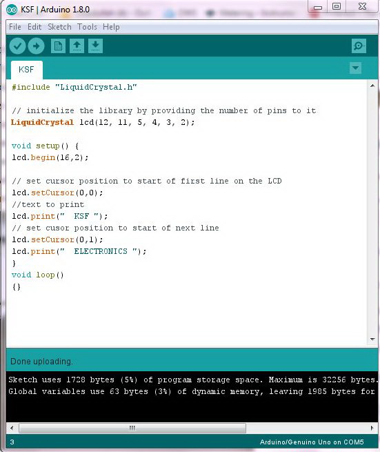
 This was my first arduino project; it was really a very big success for me in the field of electronics, Actually many guys did not have any idea to develop any best microcontroller based project, because they confused to decide which microcontroller to be used which programmer to used, also they confused about the programmer software, by using the arduino board you didn’t have to worry about the Microcontroller selection, programming software etc., you have only to develop the program, it will be compile the program burn the microcontroller & show they result , every  electronic engineer  should have  experience in the field of microcontroller , because many of electronic circuits can be developed by using microcontroller , in my this simple project I try to write the codes to show some thing on the screen,   you can configure any pin , but here I used arduino pins  2,3,4,5,11,12 & LCD pins are 14,13,12,11,6,4 were used,

  • LCD RS pin to digital pin 12
  • LCD Enable pin to digital pin 11
  • LCD D4 pin to digital pin 5
  • LCD D5 pin to digital pin 4
  • LCD D6 pin to digital pin 3
  • LCD D7 pin to digital pin 2


Sunday, 4 December 2016

FM Transmitter circuit

FM transmitter having a stable frequency & with a high power (Range) is a tough task to do , actually you can buy a high power FM transmitter , but hard to make it due to the restriction as well as parts availability in the certain areas , in my this circuit the input were taken from the Car MP3 modulator , antenna point at the PCB can be easily found , where they always printed the every point on the PCB , if not found the antenna point then you can use the field strength  meter  (FSM) , antenna will be the peak FSM reading , this signal were then given to the circuit , sometime the RF power from the MP3 found low which cannot derive the  first transistor , for this biasing required from positive supply to the transistor base to boost some hove the input signal , 30 k to 56 k resistor can be used for the biasing ,in first stage I used 2sc2407 transistor ,in the other next stages both 2sc3950 were used , very cheap transistors ,where all these transistor can work very nice in the FM range, RFC were used at the transistor collector which can be easily available in the market  RFC for FM rage will be 0.56 mh  or 0.68 mh (Micro henry)  you don’t have to wound the coil , you can use 2N2219 , 2N3866, 2N2222 instead 2sc2407 , instead of 2sc3905 , you can use 2sc1971 , 2n3553 etc.


Saturday, 26 November 2016

FM Transmitter 1 Watt ( 88 MHz - 108 MHz)

Below mention transmitter is very simple to assembled , which is consist of only 2 transistors  ( 2SC2407 & 2 SC3950 )  having a stable frequency & with a high power (Range) is a tough task to do , actually you can buy a high power FM transmitter , but hard to make it due to the restriction as well as parts availability in the certain areas , in my this circuit the input were taken from the Car MP3 modulator , antenna point at the PCB can be easily found , where they always printed the every point on the PCB , if not found the antenna point then you can use the field strength  meter  (FSM) , antenna will be the peak FSM reading , this signal were then given to the circuit , sometime the RF power from the MP3 found low which cannot derive the  first transistor , for this biasing required from positive supply to the transistor base to boost some hove the input signal , 30 k to 56 k resistor can be used for the biasing ,in first stage I used 2sc2407 transistor ,in the final stages 2sc3950 were used , very cheap transistors ,where all these transistor can work very nice in the FM range, RFC were used at the transistor collector which can be easily available in the market  RFC for FM rage will be 0.56 mh  or 0.68 mh (Micro henry)  you don’t have to wound the coil , 2-30 PF Variable capacitor ofr fixed 20 PF capacitor can be used, also you can use 2N2219 , 2N3866, 2N2222 instead 2sc2407 , also you can use 2sc1971 , 2n353 instead of 2sc3950.


Friday, 4 November 2016

DC TO DC UNINTERRUPTIBLE POWER SUPPLY (48 V DC )

One of my friend demanded to design such a project where there is two different DC power supply ,we need to have un interrupted output , this circuit is designed around 48 Vdc , both power supply input mentioned in the circuit are 48v-1 & 48v-3 , both voltages were then combined by the diode  D1 & D2 , it is then down  converted by the R2 (330R, 5W) to make it in the input Rang of LM317 IC 2 , with the R24 & R25 it output will be near 15 V , then after it 7805 IC were used for fixed 5V supply for the whole circuit. Initially if power applied to the circuit ,Relay K1 will energize due to opto-coupler direct connected to the incoming both power supply while triggering transistor T2, IC C & D  will be energized when relay K1 will activated , actually both gates of IC C & D are set as a timers , when power applied to the IC both timers will start , first timer ( C ) will will trigger T3 realy K2 will energized ,the contact of this relay (6 & 4 ) will be disconnected by resulting Q1 off , here Q1 kept off by the R28 ,will be on by the R30 , the Relay ( 200 Amps) which is (SV2-1)  is normally closed ( ON)  ( with no power ) if Q1 enabled it will results relay activated & the contacts will be separated power will be disconnected, on the other the relay  (SV2-3)  will be  activated by  Q2 from relay K3 driven by the T4 , & T4 will be activated by IC1 D ( other timer). if timer run T4 will activated relay K3  , contacts (8 & 4 ) will make , Q4 will be on , capacitor C3 will remain the relay k2 on till capacitor discharged. Buzzer SG1 will be on when relay K1 activated. Threshold voltage level be adjusted by R1   

Friday, 23 October 2015

FM / MW / SW Radio as Tri-band Transceiver ( full duplex transmission )

In this project i will introduce a full duplex radio communication from  FM / MW / SW Radio.For this we will use two radio sets ,( Digital or Analog Radio set ) just keep two radio sets near each other , tune one of the radio having same band you will observe that both radios will become silent at one tuning point , This is because of local oscillators in both radios , both radios will receive each other local oscillator frequency. Local oscillators are used in superheterodyne receiver for obtaining first IF stage (10.7 MHz ) every coming station frequency output will be remain 10.7 MHz because local oscillator frequency , than another IF stage 455 KHz  and station frequency will simultaneously tune. It means that if want to receive 100 MHz on radio , then local oscillator frequency will be 110.7 MHz , 100+10.7 = 110.7 , 110.7 MHz - 10.7 MHz = 100 MHz  ( At 100 MHz station frequency local oscillator will be having 110.7 MHz ) for having output 10.7 MHz by adding 2 or 3 stages of RF amplifiers a professional transceiver can be made specially for Car Radio. Here in this project actually local oscillator frequency will be amplified , with a fix frequency stability In this case i am going to work on Medium Wave Radio ( MW ) , Here we require 450 KHz at incoming every station , at 1413 KHz local Oscillator frequency will be 1863 KHz  it will be than mixed  & output will be 450 KHz 
1). 1863 KHz - 1413 KHz = 450 KHz  === 1413+450= 1863 KHz 
2). 1485 KHz - 1008 KHz = 450 KHz
Whole MW rang from 522 KHz to 1650 KHz  will have its local Oscillator frequencies Only 2 RF stages will added to the Local Oscillator output for Long range


Thursday, 15 October 2015

48 V DC to 5 V DC Converter circuit

  High voltage DC conversion to a low level is tough task , but it is not that difficult task so  this circuit is consist of Transistor based DC voltage  down converter circuit , here a power full transistor TIP35C were used , a smal network of resistor 4.7k , 100R 5W , Zener diode 12V, capacitor 220uf were used , Zener Diode first limited the voltages up to 12 from the input with help of TIP35C , a diode IN4001 used for protection to the circuit, this 12V were then applied to any other regulator IC like 7805 or 7809. any other other powerfull transistor be used like 2SC5200.